Making a DIY pointing stick
As an input method, pointing sticks are pretty uncommon. They’re familiar to users of ThinkPads and some Dell or HP laptops, but most other people haven’t come across them. The pointing stick is the nub in the middle of the keyboard that you push around to control the pointer. It’s quite convenient to move the pointer without needing to move your hands off the keyboard.
The problem I wanted to solve is that they’re almost exclusively available on laptops. Only two companies make external keyboard with pointing sticks - Lenovo and Tex. Some people building their own keyboards want to integrate a pointing stick. Their only option is usually to buy an old ThinkPad keyboard and remove the Trackpoint. I’d like to make it easy for anyone to include a pointing stick in their keyboard design.
The best way I can see to do that is to create an open-source pointing stick module that anyone can use. There are some pointing stick modules available, but they seem to be old stock. If I create an open source design, any keyboard designer can include it in their keyboard. It can even be tweaked to meet their needs.
This post is a summary of my initial progress creating this module. Starting with off-the-shelf strain gauge amplifiers, I then design a custom PCB and build it into a keyboard. The final product in this post isn’t ready for production, but it’s a good first step.
How do they work?
What makes a pointing stick different to a joystick? In a (resistive) joystick, movement of the stick moves the wiper of a potentiometer - usually one for each axis. The voltage from the potentiometer is proportional to the position of the stick. In a pointing stick, the movement of the stick is much smaller. It stretches and compresses strain gauges. These strain gauges are resistors which vary when stretched or compressed. The changing resistance gets amplified and then measured by a microcontroller.

You might think that this sounds complicated - why would we bother using this instead of a joystick? In a way we are - it’s just a very stiff joystick with a different way of sensing the movement. The key for me is that the stick barely moves. It makes a big difference to how it feels, making it much easier to position the pointer. You can make them much flatter than a joystick, which is why they’re used in keyboards.
Getting it working
To begin with, I needed to know if this project is even realistic. A good way to do that is to put together some off-the-shelf modules. If that works, then I can design a dedicated PCB.
Using some cheap BF350-3AA strain gauge amplifier modules, I did a first test. The mount for the strain gauges is 3D printed, with the gauges stuck on with superglue.

These amplifier boards use an LM358 dual op-amp to amplify the signal. I used Big Clive’s technique of taking photos of the PCB and drawing on them to build up a schematic of the module.


The amplifier circuit compares the voltage from the strain gauge voltage divider with another fixed one. It amplifies the difference between them by 47x. That voltage is then compared with one set by the tuning potentiometer, then amplified again by 24.5x.
There were a few interesting things about the amplifier:
- Using an opamp
- I knew what they were, but I’d never implemented one!
- Using two stages of amplification seems unnecessary.
- Apparently it’s more typical to use a dedicated instrumentation amplifier for strain gauges, but they’re a lot more expensive!
- Using a TL431 shunt voltage regulator
- These work differently to the linear regulators I’m used to
- Generating a reference voltage using a potentiometer
- This means you can calibrate it easily, but can’t make it automatically correct for drift
Designing a PCB
The amplifier design was simple, but it seemed like I could optimise it for the pointing stick. Why use two stages of amplification, when one would do? If I could adjust the reference voltage from a microcontroller, there would be no need for manual tuning.
It turns out that’s exactly what digital potentiometers are for. I breadboarded a circuit using a MCP4251 digital pot to generate a reference voltage. The microcontroller can communicate with the MCP4251 to adjust the voltage.

For once I’d actually done the work of testing all the components for a PCB before designing it! The breadboard had served its purpose, but it was very fragile - there were a few connections that could be knocked out of place far too easily. It was pretty simple to put together a schematic of what I’d built on the breadboard. I did a rough (not very good) layout and sent it off to JLCPCB for manufacture.


It wasn’t long before the PCBs arrived. I quickly soldered one up, realised it was a pain (especially the MicroUSB connector), and bought a hot air soldering station. The second board was a lot easier to assemble!


Building it onto a PCB made the readings a lot more stable and less noisy (even though my layout was badly optimised for analog readings!). It was now feasible to plug it in and use it with a computer! It felt good, but without being part of a keyboard it was hard to tell how “right” it felt.
Building it in
This is the fun part - I was finally getting close to something I could actually use! The intention was to mount the pointing stick to the bottom of a keyboard and poke the stem through a hole in the PCB. Then, much like a ThinkPad keyboard, the nub could sit between the G and H keys. I had a couple of PCBs left over from my grid60 keyboard prototypes - perfect for drilling a hole in!


With some components to avoid on the bottom side of the PCB, the mount for the strain gauges needed to make contact only in specific points. It also had to be as thin as possible, to avoid making the keyboard any taller than it needed to be.


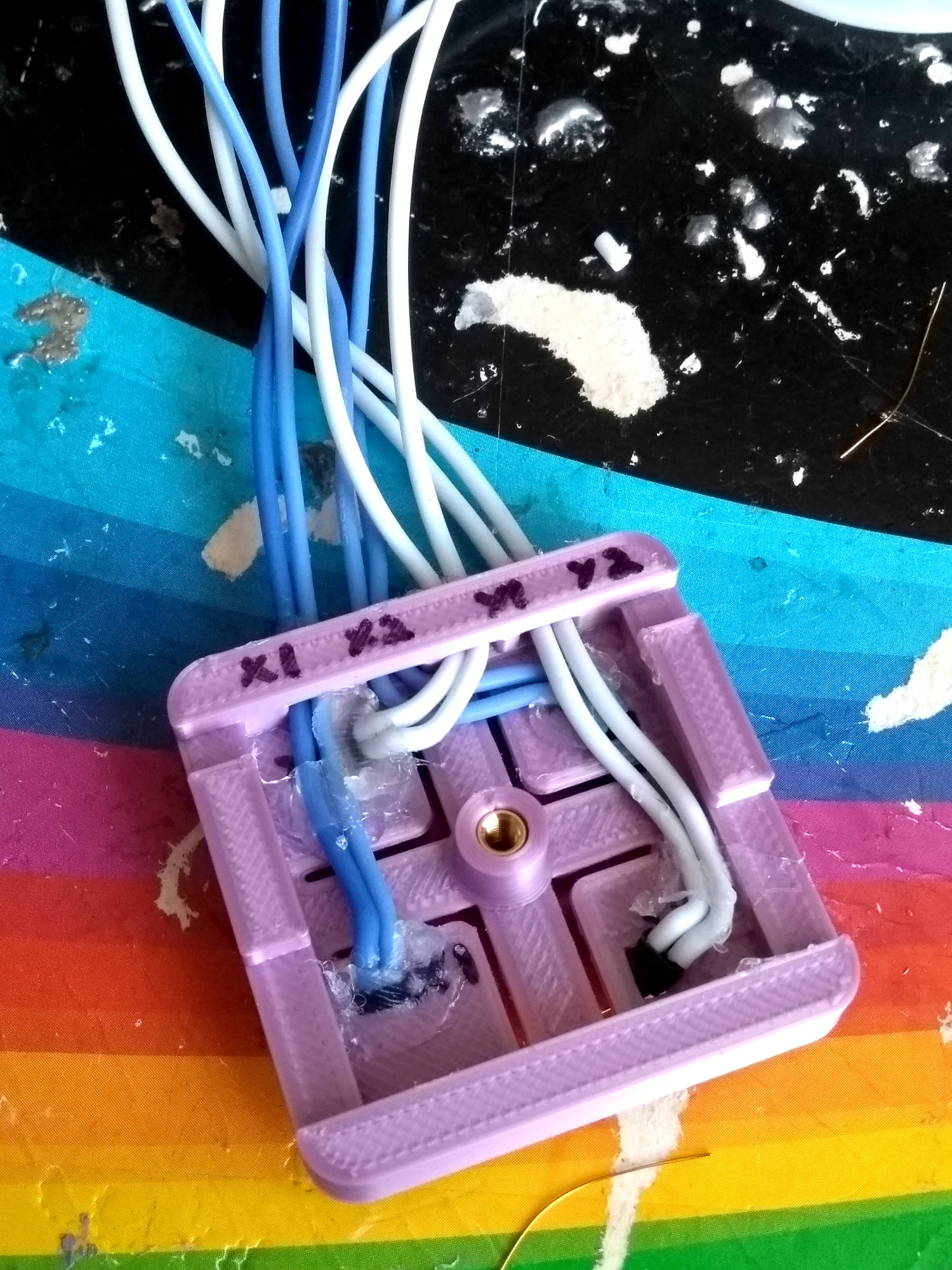
Wiring up the strain gauges takes a long time! You have to be careful not to overheat them. They’re mounted on plastic, which can melt, and they can delaminate if you overheat them. I used the thinnest wire I had, to try to avoid pulling off the pads off the gauges. That thin wire then goes to a thicker, less fragile wire.


Trying it out
It was finally time to try out a keyboard with a homemade pointing stick built in. It actually worked surprisingly well! Using it to move the cursor around the screen felt quite natural, although setting the speed was tricky. At slow speeds it had good precision but took ages to get across the screen. At higher speeds, it was quick to cross the screen but lost the precision needed for selecting text.
The physical feel wasn’t quite like a typical TrackPoint pointing stick. It takes more movement to move the cursor at a similar speed. That’s due to the longer stem and flexible strain gauge mount, as well as my measurement PCB being less sensitive.
Lastly, I noticed that some noise in the ADC measurements caused the pointer to drift over time. This is sometimes a problem on commercial pointing sticks too - it’s because of the high level of amplification needed (and in my case, the bad shielding).

Adding this low pass filter to the PCB was simple, but in the process I broke the strain gauge for the Y axis. This was the second time I’d done that, and I decided to leave this prototype. The strain gauges and connections are way too fragile for this to be a robust solution.

Going forward
When it works, this resistive strain gauge design works well! It’s quite nimble for text selection, and felt about as natural to use as my ThinkPad’s TrackPoint. The jitter in the pointer is mostly solved by the low pass filter, but it might still be present. I had some ideas for detecting and correcting the drift in software, but they turned out to be too aggressive and caused more drift than they removed!
The big problem with these strain gauges is that they’re fragile. It’s definitely not a design that would work for an actual product. It’s fiddly and time-consuming to connect, and not robust enough to mechanical stress. I wouldn’t recommend building this into your keyboard unless you really want to try it out!
There are a few things that are worth looking at in future iterations of this project:
- Adjusting acceleration curves in firmware, rather than using the operating system’s acceleration.
- This would make it easier to get high precision at low speeds and still be able to reach high speeds.
- Improved stiffness of the strain gauge mounts, coupled with better acceleration
- Less movement would make it feel less “spongy” or joystick-like.
- Spring connections to the strain gauges
- This would just make it a lot easier to assemble! I’m not sure whether it would be consistent enough.
- Capacitive sensing
- Pointing stick manufacturers moved on to capacitive versions. They use varying distances to change a capacitance instead of a resistance. It means the fiddly strain gauges can be eliminated!
- Connecting to keyboard microcontroller over i2c
- I implemented a basic i2c interface, but it would be good to develop it further. It would be cool to have a QMK/ZMK keyboard talking to the pointing stick, so you only need one USB cable.
This is a good first step towards an open-source pointing stick, but I’m going to leave the next one for another time. But speaking of open-source, here's the repository on Gitlab!